
Power redundancy is one of the most important considerations when designing a reliable data center rack.
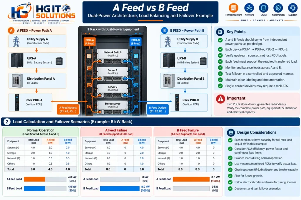
In many enterprise environments, servers, storage systems, network switches, and other critical devices are equipped with two power supply units (PSUs). These devices are often connected to two separate rack power distribution units (PDUs), commonly identified as A Feed and B Feed.
At first glance, this arrangement appears simple: connect one power cord to A and the other to B.
However, a properly designed dual-power system requires much more than two PDUs and two power cords.
What happens if both rack PDUs are connected to the same upstream breaker? Can the B Feed support the complete rack load if A fails? What if a server has two power supplies but cannot operate at full load on one? How can an installation team confirm that both power paths are genuinely independent?
These are practical engineering questions that must be addressed before equipment is commissioned.
This guide explains A Feed vs B Feed, how dual-power paths work inside a data center rack, how to plan redundant power distribution, and how to avoid hidden single points of failure.
Table of Contents
1. What Is A Feed and B Feed in a Data Center?
A Feed and B Feed are commonly used labels for two electrical supply paths serving critical IT equipment.
The labels identify the paths. They do not, by themselves, establish that the paths are electrically independent or redundant.
In a typical dual-corded rack configuration:
- A Feed supplies Rack PDU-A.
- B Feed supplies Rack PDU-B.
- Server PSU-1 connects to PDU-A.
- Server PSU-2 connects to PDU-B.
If the equipment and upstream infrastructure are designed correctly, a failure or planned isolation of one power path should not interrupt the protected IT workload.
The exact redundancy behavior depends on the power architecture, PSU design, load distribution, and available capacity.
A Feed vs B Feed: Quick Comparison
| Parameter | A Feed | B Feed |
|---|---|---|
| Identification | Power Path A | Power Path B |
| Typical rack connection | Rack PDU-A | Rack PDU-B |
| Typical equipment connection | PSU-1 | PSU-2 |
| Normal operation | May share equipment load | May share equipment load |
| During opposite-feed failure | Must support required transferred load | Must support required transferred load |
| Upstream source | Design-specific | Design-specific |
| Required verification | Source, protection, capacity | Source, protection, capacity |
Important: A Feed is not automatically the primary source, and B Feed is not automatically a standby source.
Many dual-corded IT devices draw power from both feeds during normal operation.
The terms primary and secondary should only be used when they accurately describe the equipment and approved electrical design.
2. Why Dual-Power Paths Matter
A single electrical path can contain multiple failure points.
These may include:
- UPS equipment
- Distribution boards
- Circuit breakers
- Busways or power cables
- Rack PDU input connections
- Rack PDU internal components
- Equipment power cords
- Individual power supply units
If critical equipment depends on only one path, a failure anywhere along that path may interrupt the service.
A correctly designed dual-power architecture can reduce exposure to these failures by providing an alternative supply path.
The benefits may include improved equipment availability, better maintenance flexibility, and reduced dependence on individual electrical components.
However, the system must be evaluated end to end.
Two power cords do not automatically provide two independent power paths.
3. Understanding the Complete Power Path
A rack PDU is only the final distribution component in a larger electrical system.
A simplified dual-path architecture may look like this:
Power Path A
UPS System A → Distribution Board A → Protected Circuit A → Rack PDU-A → Server PSU-1
Power Path B
UPS System B → Distribution Board B → Protected Circuit B → Rack PDU-B → Server PSU-2
This is a conceptual example, not a mandatory architecture for every data center.
Actual systems may include transformers, switchboards, remote power panels, busways, generators, transfer equipment, and other distribution components.
The critical requirement is to understand which components are shared and which are independent.
For example, two rack PDUs may connect to different distribution boards but still depend on the same upstream UPS output.
In that case, the rack has two local distribution paths but may retain an upstream single point of failure.
A power-path diagram should identify these dependencies before redundancy claims are made.

4. Dual Rack PDUs Do Not Guarantee Redundancy
Consider a rack with two vertical PDUs.
Both are labeled correctly:
- PDU-A
- PDU-B
Each server has two power cords, with one connected to each PDU.
The installation may appear redundant.
But suppose both PDUs are supplied from the same distribution circuit or upstream device.
If that common component fails, both PDUs may lose power simultaneously.
The rack therefore contains a hidden single point of failure.
This is why engineers must verify the upstream source of each rack PDU rather than relying only on labels.
What should be checked?
- Rack PDU source identification
- Distribution board and circuit references
- UPS or upstream source relationships
- Breaker assignments
- Cable and busway routing
- Common upstream dependencies
- Approved electrical single-line diagrams
The objective is to confirm the actual redundancy boundary.
5. How Dual-Power Servers Work
Many enterprise servers use redundant power supply modules.
A common configuration contains two PSUs, each connected to a separate rack power path.
During normal operation, the PSUs may share the electrical load.
For example, a server consuming 600W might draw approximately 300W from each feed in a balanced operating mode.
If one feed fails, the surviving PSU may need to supply the full 600W.
However, PSU behavior varies by equipment manufacturer and configuration.
Some systems support active-active load sharing. Others use different power-sharing or redundancy modes.
Therefore, technicians must confirm that:
- Each PSU has sufficient capacity for the required equipment load.
- The server supports continued operation after losing one input.
- PSU redundancy is enabled or configured correctly where applicable.
- The surviving feed can support the resulting demand.
Never assume that two installed PSUs automatically provide full redundancy at every possible equipment load.
6. Active-Active vs Active-Standby Power Behavior
Dual-power equipment can operate in different ways.
Active-active operation
In an active-active arrangement, both PSUs contribute to the load during normal operation.
If one power path is lost, the surviving supply must increase its output to maintain operation.
Active-standby operation
In some equipment designs, one power supply carries most or all of the load while the other remains available for backup.
The standby supply may become active when the preferred supply fails.
Why this matters
The power distribution design must account for actual equipment behavior.
For example, a rack containing several active-standby devices may have a significantly unbalanced A/B load even when every device is connected correctly.
An installation team should not expect a 50/50 load split without checking the equipment specifications and measured PDU readings.
7. The Most Important Rule: Surviving-Feed Capacity
One of the most serious dual-power design mistakes is sizing each feed only for its normal operating load.
Suppose a rack consumes 8kW in total.
During normal operation, the load may be approximately:
- A Feed: 4kW
- B Feed: 4kW
If A Feed fails, the B Feed may need to support the entire 8kW.
If B Feed is only capable of delivering 5kW under the applicable operating limits, the design is not sufficient for this failure scenario.
Practical example
| Parameter | Normal Operation | After A Feed Failure |
|---|---|---|
| Rack total load | 8kW | 8kW |
| A Feed | 4kW | 0kW |
| B Feed | 4kW | 8kW |
| Required B capacity | At least normal B demand | Full transferred demand |
This example assumes the protected equipment continues operating at the same total load.
In real installations, engineers must also consider PSU efficiency, input current, voltage, power factor, transient behavior, and applicable circuit-loading limits.
Each surviving power path must be capable of carrying the required load within its approved electrical limits.
This applies to the complete path, not just the rack PDU nameplate.
8. Understanding the 50% Loading Principle
In a balanced dual-feed architecture, a useful planning concept is to reserve enough capacity for the complete load to transfer to either path.
For example, if both feeds are equally rated and the equipment normally shares the load evenly, each feed may operate at approximately half of its allowable capacity.
However, the phrase “50% loading” must be interpreted carefully.
The allowable load depends on the circuit design, breaker characteristics, continuous-load rules, manufacturer specifications, and applicable electrical codes.
A circuit rated at 32A does not automatically permit 32A of continuous operating current under every installation condition.
Example: Conceptual capacity calculation
Assume a single-phase rack power circuit has:
- Nominal voltage: 230V
- Nominal current rating: 32A
Its nominal apparent-power rating is:
230V × 32A = 7,360VA
That is 7.36kVA, not automatically 7.36kW of usable continuous IT power.
The allowable continuous operating capacity must be established using the applicable electrical design rules and equipment ratings.
Once that allowable capacity is determined, the total transferred rack load must remain within it.
This is a more reliable approach than applying a universal percentage without considering the electrical system.
9. Single-Phase vs Three-Phase A/B Feeds
Data center racks may receive single-phase or three-phase electrical supplies.
The correct choice depends on rack power density, equipment requirements, facility distribution architecture, and local electrical standards.
Single-phase distribution
Single-phase rack PDUs may be appropriate for moderate equipment loads.
They are commonly used where the available electrical capacity and outlet configuration satisfy the deployment requirements.
Three-phase distribution
Three-phase rack PDUs can support higher aggregate power requirements and provide additional flexibility for distributing single-phase outlet loads across phases.
However, three-phase installations introduce phase-balancing considerations.
The installation team must verify:
- Phase allocation
- Line and phase currents
- Neutral loading where applicable
- PDU outlet phase mapping
- Circuit and connector compatibility
- Transfer-load behavior
A three-phase PDU does not eliminate the need to size each A/B path for its required failure scenario.
10. Rack PDU Selection for Dual-Power Designs
The rack PDU must be selected based on the electrical design and actual equipment requirements.
Important parameters include:
| Selection Parameter | Engineering Consideration |
|---|---|
| Input voltage | Must match approved supply |
| Input phase | Single-phase or three-phase |
| Input connector | Compatible with circuit and PDU rating |
| Rated current | Suitable for planned load |
| Outlet types | Compatible with equipment cords |
| Outlet quantity | Supports present and future equipment |
| Mounting format | Vertical or horizontal |
| Metering | Enables load verification |
| Monitoring | Supports operational visibility |
| Switching | Only where operationally appropriate |
Metered or monitored PDUs can help operators observe current, power, and other measurements.
However, monitoring features do not replace correct circuit protection or electrical capacity planning.
The rack PDU must also be installed in accordance with its manufacturer’s instructions.
11. Correct A/B Power Cord Connections
For a conventional dual-PSU server, the intended connection may be:
Server PSU-1 → Rack PDU-A
Server PSU-2 → Rack PDU-B
This should be confirmed against the approved rack power schedule and equipment installation requirements.
Common connection mistake
Both server power cords are connected to PDU-A.
The server has two active PSUs, but both depend on the same rack PDU.
If PDU-A fails, the server may shut down even though PDU-B remains operational.
Another common mistake is connecting the two PDUs to different outlets that share an upstream single point of failure.
The correct approach is to trace and document the complete source-to-equipment relationship.

12. A/B Power Cable Routing Inside the Rack
Good cable management is essential for both reliability and maintainability.
A and B power cords should be clearly identified and routed according to the approved installation design.
Where practical, physical separation can reduce the risk of both paths being affected by the same local incident or maintenance activity.
However, the required separation depends on the facility design and applicable standards.
Recommended cable-management practices
- Use consistent A/B identification.
- Avoid unnecessary power-cord crossing.
- Keep cables away from sharp edges.
- Maintain appropriate bend radius.
- Prevent strain on equipment power connectors.
- Use manufacturer-approved cable-retention accessories.
- Keep PDU outlets accessible.
- Avoid obstructing equipment airflow.
- Document each power-cord connection.
Cable routing should also consider equipment removal and replacement.
A server should not require unnecessary disturbance of adjacent power connections during routine maintenance.
13. Power Feed Labeling and Identification
Clear labeling reduces the risk of incorrect connections and maintenance errors.
A practical labeling scheme may include:
- Rack identifier
- Power path identifier
- Rack PDU identifier
- Source distribution board
- Circuit reference
- Equipment PSU connection
Example
| Component | Example Label |
|---|---|
| Rack | DC-R01-RK05 |
| A-side PDU | DC-R01-RK05-PDU-A |
| B-side PDU | DC-R01-RK05-PDU-B |
| A circuit | DB-A / Circuit 12 |
| B circuit | DB-B / Circuit 18 |
These labels are illustrative.
Actual naming conventions should follow the facility’s approved documentation standards.
Some organizations use different cable or outlet colors to distinguish A and B.
Color coding can help, but it should never replace readable labels and verified circuit identification.
14. How to Document a Rack Power Schedule
A rack power schedule should record the relationship between each equipment PSU and its supply path.
Example rack power schedule
| Device | PSU | Rack PDU | Outlet |
|---|---|---|---|
| Server-01 | PSU-1 | PDU-A | A01 |
| Server-01 | PSU-2 | PDU-B | B01 |
| Server-02 | PSU-1 | PDU-A | A02 |
| Server-02 | PSU-2 | PDU-B | B02 |
| Storage-01 | PSU-1 | PDU-A | A03 |
| Storage-01 | PSU-2 | PDU-B | B03 |
A more complete production record may also include:
- Equipment asset ID
- Rack location
- PDU model and serial number
- Source circuit
- Rated equipment input
- Measured load
- Power-cord type
- Installation date
- Verification status
These records support maintenance, troubleshooting, capacity planning, and infrastructure audits.
15. Single-Corded Equipment in a Dual-Power Rack
Not every device has two power supplies.
Some network appliances, console devices, small servers, and specialized systems use a single power cord.
Connecting a single-corded device to PDU-A does not make it redundant simply because PDU-B is present.
If A fails, the device loses power.
What about an Automatic Transfer Switch?
A properly selected rack-mounted Automatic Transfer Switch (ATS) can supply a compatible single-corded device from one of two available input sources.
If the preferred source fails, the ATS may transfer the load to the alternate source.
However, an ATS introduces its own design considerations:
- Transfer characteristics
- Equipment tolerance to interruption
- Input source compatibility
- Output loading
- Protection coordination
- Failure modes
- Maintenance requirements
An ATS does not convert a single-PSU device into a fully dual-corded device.
It can reduce exposure to some supply-path failures, but the ATS and downstream single power cord remain potential failure points.
The correct approach depends on the workload’s availability requirements.
16. Common A/B Feed Design Mistakes
Mistake 1: Both PDUs share the same upstream source
Two rack PDUs may appear independent while sharing a critical upstream component.
Mistake 2: Both server cords connect to the same PDU
This defeats the intended rack-level A/B connection arrangement.
Mistake 3: The surviving feed cannot carry the complete load
The rack operates normally until one feed fails and the remaining path becomes overloaded.
Mistake 4: PSU redundancy is assumed rather than verified
Two PSUs may not support the full operating load individually under every configuration.
Mistake 5: Power loads are estimated only from nameplate ratings
Nameplate values are useful for compatibility and maximum-input considerations, but actual operating demand should be evaluated using approved design assumptions and measured data.
Mistake 6: A/B labels are inconsistent
Incorrect labeling can cause maintenance teams to isolate the wrong source.
Mistake 7: Three-phase loads are poorly balanced
Uneven phase loading can limit available capacity and complicate failover planning.
Mistake 8: Single-corded devices are overlooked
A single-corded device may remain a critical single point of failure despite the rack’s dual-feed infrastructure.
Mistake 9: No approved failover verification exists
The installation may be documented as redundant without evidence that the intended failure scenarios have been assessed.
17. Practical Example: Designing A/B Power for a 10kW Rack
Consider a hypothetical rack with a planned IT load of 10kW.
Assume all protected equipment is dual-corded and supports continued operation on either input path.
During balanced normal operation:
- A Feed supplies approximately 5kW.
- B Feed supplies approximately 5kW.
If A Feed is lost:
- A Feed supplies 0kW.
- B Feed must support approximately 10kW.
If B Feed is lost:
- B Feed supplies 0kW.
- A Feed must support approximately 10kW.
Design review
| Requirement | Design Check |
|---|---|
| Total rack demand | 10kW |
| Normal A demand | Approximately 5kW |
| Normal B demand | Approximately 5kW |
| A-path failure case | B supports required full load |
| B-path failure case | A supports required full load |
| PSU compatibility | Each device survives one input loss |
| Electrical protection | Suitable for normal and transfer conditions |
| Monitoring | A/B and phase measurements available |
| Documentation | Source and outlet mapping complete |
This is a simplified illustration, not a final electrical design.
In production, each path must be evaluated for its allowable continuous capacity, operating voltage, power factor, equipment efficiency, growth allowance, protective-device characteristics, and any relevant transient conditions.
The load must also remain within the capacity of upstream UPS, distribution, and other electrical components.
18. Verifying A/B Power Redundancy Before Commissioning
Redundancy should be demonstrated through an approved commissioning and verification process.
The first step is a documentation review.
Confirm that the electrical single-line diagram, rack power schedule, PDU labels, and equipment PSU connections agree.
Next, review available monitoring data to establish the normal operating conditions.
Typical checks include:
- A-side current and power
- B-side current and power
- Phase loading where applicable
- Equipment PSU health
- UPS and distribution alarms
- Available capacity under a single-path failure
What about failover testing?
A controlled power-path interruption may be part of a formal commissioning procedure.
However, deliberately disconnecting live rack power without an approved method can cause equipment outages, electrical hazards, and unexpected downstream effects.
Any such test should be performed only by authorized personnel under an approved Method of Procedure (MOP), with appropriate electrical safety controls, risk assessment, rollback arrangements, and stakeholder approval.
For live production environments, non-disruptive verification and historical test evidence may be more appropriate until a controlled maintenance window is available.
The purpose of testing is to verify the approved design—not to create unnecessary risk.
19. A/B Feed Design and Data Center Availability
Dual-power distribution is closely associated with high-availability data center design.
However, a dual-feed rack alone does not establish a facility’s availability classification.
The broader infrastructure must be considered, including:
- Utility and generator arrangements
- UPS architecture
- Distribution-path independence
- Cooling infrastructure
- Maintenance requirements
- Fault isolation
- Operational procedures
For example, Uptime Institute’s Tier III concept includes concurrent maintainability, while Tier IV adds fault-tolerance requirements.
These classifications apply to the facility’s infrastructure topology and performance objectives, not simply the number of PDUs installed in a cabinet.
A rack should not be described as “Tier III compliant” solely because it has A and B feeds.
20. A/B Power Feed Installation Checklist
Use this checklist during design review, rack deployment, and pre-commissioning verification.
Power source verification
- A and B sources identified
- Approved single-line diagram reviewed
- Shared upstream dependencies documented
- Distribution board and circuit references confirmed
- Required redundancy objectives understood
Electrical capacity
- Rack demand calculated
- A-path capacity verified
- B-path capacity verified
- Single-path failure loading evaluated
- Applicable continuous-load limits checked
- Three-phase balance reviewed where applicable
Rack PDU installation
- PDU electrical ratings verified
- Input connectors and circuits compatible
- PDU mounting positions approved
- Outlet quantities and types confirmed
- Monitoring configured where available
- PDU labels installed
Equipment connections
- PSU redundancy verified
- PSU-1 connected to the assigned A path
- PSU-2 connected to the assigned B path
- Single-corded equipment identified
- Power cords secured and accessible
- Power connections documented
Commissioning and operations
- Rack power schedule completed
- Monitoring baseline recorded
- Alarm thresholds reviewed
- Failure scenarios evaluated
- Approved commissioning evidence retained
- As-built documentation updated
21. Industry References and Further Reading
For additional technical guidance, the following resources provide useful information about dual-power distribution and equipment redundancy.
Schneider Electric — Rack Powering Options for High Density
This white paper discusses rack power distribution alternatives, feed quantities, breaker arrangements, electrical loading, and redundancy considerations.
Uptime Institute — Dual-Corded Power and Fault Tolerance
This article discusses dual-corded IT equipment, power-path reliability, operational practices, and the importance of correctly connecting equipment to separate distribution paths.
Vertiv — How to Avoid Downtime With Redundant Rack PDUs
This reference explains rack PDU redundancy, loading considerations, and the importance of properly managing redundant power infrastructure.
These references should be used alongside current manufacturer documentation, approved project drawings, and applicable electrical codes.
Final Thoughts
A Feed and B Feed are fundamental concepts in reliable data center rack power design.
However, installing two rack PDUs and connecting two server power cords is only the beginning.
True dual-power resilience depends on the entire electrical path, equipment PSU behavior, available capacity, protection coordination, accurate labeling, and operational verification.
The most important questions are not simply whether the rack has two feeds.
They are:
Can the protected equipment continue operating when either power path is unavailable?
Can the surviving electrical path safely support the resulting demand?
Are the actual upstream dependencies understood and documented?
When these questions are addressed during design, installation, and commissioning, dual-power distribution becomes a meaningful part of data center reliability rather than merely a pair of labeled PDUs.
Frequently Asked Questions
1. What is the difference between A Feed and B Feed?
A Feed and B Feed identify two electrical supply paths. Their purpose is to support redundancy where the infrastructure and connected equipment are designed appropriately. Neither label automatically means primary or backup.
2. Do A and B feeds always come from separate UPS systems?
No. The upstream arrangement depends on the facility architecture. Two rack feeds may have separate distribution components but still share an upstream source. The approved single-line diagram must be reviewed.
3. Should each feed support 100% of the rack load?
For a design intended to survive the complete loss of either path without interrupting protected equipment, each surviving path must support the required transferred demand within its approved operating limits.
4. Can both server power supplies connect to the same rack PDU?
They may operate electrically, but doing so generally defeats the intended rack-level A/B redundancy because both supplies depend on the same PDU.
5. What happens when A Feed fails?
For correctly designed and configured dual-corded equipment, the surviving B path should continue supplying the required load. Actual behavior depends on the equipment and electrical design.
6. Can single-corded equipment use A/B feeds?
A compatible transfer switch can provide source selection for some single-corded devices. However, this does not eliminate all single points of failure.
7. Is A/B power distribution the same as 2N redundancy?
Not necessarily. A/B identifies separate power paths, while 2N describes a broader capacity-redundancy architecture. The complete upstream system must be evaluated before applying a 2N designation.
8. How do technicians verify A/B feed redundancy?
They review source documentation, electrical capacity, PSU compatibility, rack PDU monitoring, circuit mappings, and approved commissioning evidence. Any live interruption test requires a controlled, authorized procedure.
Continue Learning With HG IT Solutions
Reliable rack power distribution is closely connected to rack selection, equipment placement, installation planning, and long-term data center operations.
Explore our related guides:
Data Center Rack Installation Checklist: Complete Pre-Installation Guide
Data Center Rack Size Guide: 42U, 45U, 48U, Width & Depth
Data Center Rack Size Guide: 42U vs 45U vs 48U
Related upcoming guides:
- Data Center Rack Power Planning: A/B Feeds, Capacity & Redundancy
- Rack PDU Installation & Placement: A Practical Guide
- Rack Power Load Balancing Across Phases: A Practical Guide
Published by HG IT Solutions — IT Infrastructure, Data Center, Networking, DCIM & Technical Operations.
Technical disclaimer: This guide is intended for education and infrastructure planning. Electrical design, installation, isolation, testing, and commissioning must follow applicable codes, approved project documentation, manufacturer instructions, and site-specific safety procedures. Work on energized electrical systems must be restricted to appropriately qualified and authorized personnel.
