
1. Introduction
When planning a structured cabling installation, selecting Category 6A cable is only the first decision. The next question can be more complicated:
Should you install Cat6A U/UTP, F/UTP, or S/FTP cable?
All three cable constructions can be used in a standards-compliant Cat6A cabling system capable of supporting 10GBASE-T Ethernet over a 100-meter channel. However, they differ significantly in electromagnetic interference protection, physical construction, installation requirements, bonding, termination, and overall project cost.
In a typical office environment, a well-designed Cat6A U/UTP system may be sufficient. In an industrial facility with significant electrical interference, a screened solution may provide additional protection. In a high-density data center, the decision depends on cable pathways, equipment, available rack space, interference exposure, and the complete cabling architecture.
One common mistake is assuming that the cable with the most shielding must always be the best.
That is not necessarily true.
Shielding can improve electromagnetic compatibility, but it also introduces installation responsibilities. A poorly terminated shielded cable may deliver worse practical results than a properly installed and certified unshielded cable.
In this guide, we will compare Cat6A U/UTP, F/UTP, and S/FTP from a practical engineering perspective, including:
- Cable construction and shielding differences
- EMI, RFI, crosstalk, and alien crosstalk
- 10GbE transmission performance
- Grounding, bonding, and shield continuity
- PoE++ applications and cable heating
- Data center, enterprise, and industrial use cases
- Installation complexity and project cost
- Cable certification and troubleshooting
- A practical engineering selection framework
The objective is to help network engineers, structured cabling designers, data center professionals, and installation teams select the right cable for the actual environment rather than relying only on product marketing claims.
Table of Contents
2. Understanding Cat6A Cable Shielding Terminology
Before comparing cable constructions, it is important to understand how shielding designations work.
The terminology follows a commonly used format defined in ISO/IEC cabling conventions:
XX/YYY
The portion before the slash describes the overall cable screen, while the portion after the slash describes shielding around the individual twisted pairs.
The letters have specific meanings:
| Symbol | Meaning |
|---|---|
| U | Unscreened or unshielded |
| F | Foil screen |
| S | Braided screen |
| SF | Combined braided and foil overall screen |
| TP | Twisted pair |
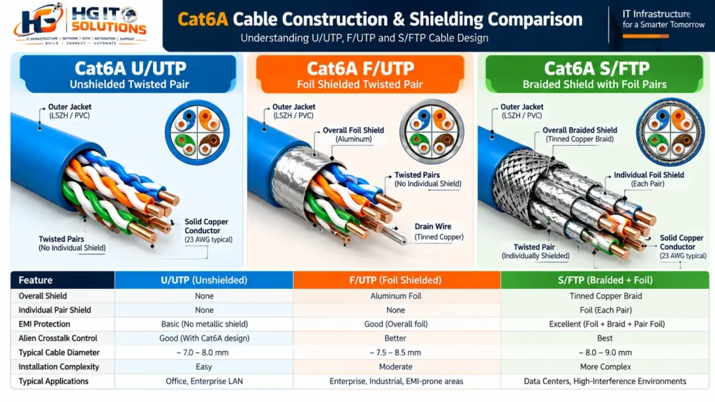
For example:
U/UTP means that the cable has no overall shield and no individual pair shields.
F/UTP means that the cable has an overall foil shield, but the individual twisted pairs are not separately shielded.
S/FTP means that the cable has an overall braided screen and individual foil screens around its twisted pairs.
These terms describe cable construction. They do not independently define the Ethernet speed or performance category.
A Cat6A cable can use different shielding arrangements while still meeting Category 6A transmission requirements.
When comparing Cat6A U/UTP vs F/UTP vs S/FTP, the most important distinction is how each cable manages electromagnetic interference. U/UTP relies on balanced twisted-pair construction, F/UTP adds an overall foil screen, and S/FTP combines individually foil-shielded pairs with an overall braided screen.
Important distinction: Category vs shielding
Category 6A specifies transmission performance up to 500 MHz.
Shielding describes how the cable is physically constructed to manage electromagnetic interference and unwanted signal coupling.
Therefore:
Cat6A = transmission performance category.
U/UTP, F/UTP, or S/FTP = cable screening construction.
The two specifications must be evaluated together.
3. Cat6A U/UTP: Unshielded Twisted Pair
Cat6A U/UTP contains four twisted pairs without an overall metallic shield or individual pair screens.
Its interference resistance comes primarily from balanced transmission, pair twisting, cable geometry, and the performance of the complete cabling system.
Manufacturers may use separators, controlled pair spacing, or other mechanical design techniques to meet Cat6A requirements, particularly for alien crosstalk.
How U/UTP reduces interference
Ethernet over twisted-pair copper uses balanced differential signaling.
The receiver evaluates the voltage difference between conductors in a pair. When external interference couples similarly onto both conductors, the receiver can reject much of that common-mode noise.
The twisting also helps reduce electromagnetic coupling.
This is why a well-designed unshielded cable can perform reliably without a metallic shield.
However, the effectiveness depends on the complete channel, cable balance, installation conditions, and the severity of external interference.
Advantages of Cat6A U/UTP
- No metallic cable shield requiring termination.
- Often simpler connector termination.
- Can be cost-effective for standard enterprise installations.
- Avoids the additional shield continuity requirements of screened cabling.
- Supports compliant 10GBASE-T channels up to 100 meters.
- Suitable for many offices, telecommunications rooms, and enterprise networks.
Limitations of Cat6A U/UTP
- No metallic screening barrier against external electromagnetic fields.
- Alien crosstalk control depends heavily on cable design and installation quality.
- Some Cat6A U/UTP products use larger cable diameters to maintain performance.
- High-interference environments may justify a screened cabling system.
Practical example: Enterprise office deployment
Consider a new office floor with 150 workstations, wireless access points, printers, and IP telephones.
The horizontal cabling runs through dedicated pathways with appropriate separation from electrical distribution systems.
The longest permanent link is approximately 75 meters.
The network currently operates at 1GbE, with selected future connections expected to use 10GBASE-T.
In this situation, a certified Cat6A U/UTP system can be a suitable choice.
There is no technical reason to specify S/FTP solely because the project may use 10GbE.
The important requirements are category compliance, installation quality, pathway design, and successful certification.
4. Cat6A F/UTP: Overall Foil Shielding
Cat6A F/UTP contains four unshielded twisted pairs surrounded by an overall metallic foil screen.
The foil is typically aluminum-based laminate, although construction details vary between manufacturers.
A drain wire may be incorporated to support screen continuity, depending on the product design.
The overall foil screen helps reduce electromagnetic coupling between the cable conductors and the surrounding environment.
How F/UTP shielding works
The foil forms a conductive screen around the cable core.
When correctly integrated into a screened cabling system, it can reduce the coupling of unwanted electromagnetic energy into and out of the cable.
This can be useful in environments where the cable route is exposed to elevated electrical noise.
It also helps reduce coupling between neighboring cables, which can benefit alien crosstalk performance.
However, the screen is only one part of the solution.
The connectors, patch panels, patch cords, equipment interfaces, and bonding arrangement must be compatible with the selected screened cabling architecture.
Advantages of Cat6A F/UTP
- Overall foil screening provides additional EMI protection.
- Can help control alien crosstalk in dense cable installations.
- Offers a practical screened-cabling option for many enterprise and industrial environments.
- May provide a useful balance between shielding and cable construction complexity.
- Supports 10GBASE-T when the complete channel meets Cat6A requirements.
Limitations of Cat6A F/UTP
- Requires compatible screened connectivity components.
- Screen termination quality affects electromagnetic performance.
- Foil can be damaged by poor handling or excessive bending.
- Bonding and grounding requirements must be addressed during design.
- Installation and material costs may be higher than for comparable unshielded systems.
Practical example: Cabling near electrical equipment
Imagine a telecommunications room serving an industrial facility.
Several cable pathways pass through areas containing electrical distribution equipment and motor-driven machinery.
Although proper cable separation and routing should remain the first design considerations, additional screening may be beneficial where the electromagnetic environment is demanding.
A Cat6A F/UTP system could be a reasonable candidate.
However, it should not be selected without reviewing the actual interference sources, pathway separation, applicable installation standards, and manufacturer’s bonding recommendations.
Shielding is not a substitute for proper cable routing.
5. Cat6A S/FTP: Braided Overall Screen with Individually Foil-Shielded Pairs
Cat6A S/FTP has a more complex construction.
Each twisted pair is individually surrounded by a foil screen, while an overall metallic braid surrounds the group of four pairs.
This provides two different levels of screening.
The individual foil screens help reduce electromagnetic coupling between pairs.
The overall braid provides additional screening against external interference and helps control electromagnetic emissions.
How S/FTP differs from F/UTP
F/UTP has one overall foil screen.
S/FTP has individual foil screens around each pair plus an overall braided screen.
These are different physical constructions, not simply different thicknesses of the same shield.
S/FTP is frequently considered for demanding electromagnetic environments, high-density cabling, and projects where a screened cabling architecture is explicitly specified.
However, actual screening effectiveness varies by product design, screen coverage, termination quality, frequency, and installation conditions.
Advantages of Cat6A S/FTP
- Individual pair screening can reduce unwanted coupling between pairs.
- Overall braid provides additional electromagnetic screening.
- Can be useful in demanding EMI environments.
- May offer strong coupling attenuation when installed as a complete compatible system.
- Supports Cat6A transmission performance when the channel is properly designed and certified.
Limitations of Cat6A S/FTP
- More complex construction and termination.
- Requires appropriate screened connectors and accessories.
- Shield preparation and termination demand greater installer attention.
- Material and installation costs can be higher.
- Cable flexibility and diameter depend on the specific product.
- Correct bonding and screen continuity remain essential.
Practical example: Industrial control network
Consider an industrial network serving production equipment, control cabinets, and monitoring systems.
The facility contains variable-frequency drives, motors, switching equipment, and other sources of electrical noise.
Where physical separation, routing, and electromagnetic compatibility analysis indicate the need for additional screening, S/FTP may be an appropriate choice.
However, engineers must still consider industrial Ethernet requirements, equipment compatibility, grounding topology, and potential differences in electrical potential between connected locations.
In some cases, fiber optic cabling may be a better engineering solution.
6. Cat6A U/UTP vs F/UTP vs S/FTP: Technical Comparison
The following table summarizes the practical differences.
| Parameter | U/UTP | F/UTP | S/FTP |
|---|---|---|---|
| Overall shield | None | Foil | Braid |
| Individual pair shield | None | None | Foil |
| Cat6A frequency | 500 MHz | 500 MHz | 500 MHz |
| 10GBASE-T support | Up to 100 m | Up to 100 m | Up to 100 m |
| EMI screening | No metallic screen | Overall foil screening | Pair foil + overall braid |
| Alien crosstalk control | Cable design and geometry | Design plus foil screening | Design plus multiple screens |
| Screen continuity | Not applicable | Required | Required |
| Screened connectors | Not required | Required | Required |
| Termination complexity | Generally lower | Moderate | Often higher |
| Cable flexibility | Product-dependent | Product-dependent | Product-dependent |
| Relative material cost | Often lower | Often moderate | Often higher |
| Typical application | General enterprise LAN | Screened enterprise/industrial | Demanding screened installations |
Note: These are general construction comparisons, not guaranteed rankings of product performance. Actual dimensions, cost, electromagnetic performance, and installation characteristics must be verified against the manufacturer’s datasheet.
The Cat6A U/UTP vs F/UTP vs S/FTP comparison demonstrates that shielding construction does not determine Ethernet speed. All three can support 10GBASE-T when installed as part of a standards-compliant Category 6A channel.
Which one provides the best Ethernet speed?
For a compliant Cat6A 10GBASE-T channel, all three constructions can support the same nominal Ethernet data rate.
S/FTP does not automatically provide higher throughput than U/UTP.
A 10GbE connection over a compliant U/UTP channel is still a 10GbE connection.
The shielding choice primarily concerns electromagnetic compatibility, physical installation, and system design rather than increasing the Ethernet port speed.
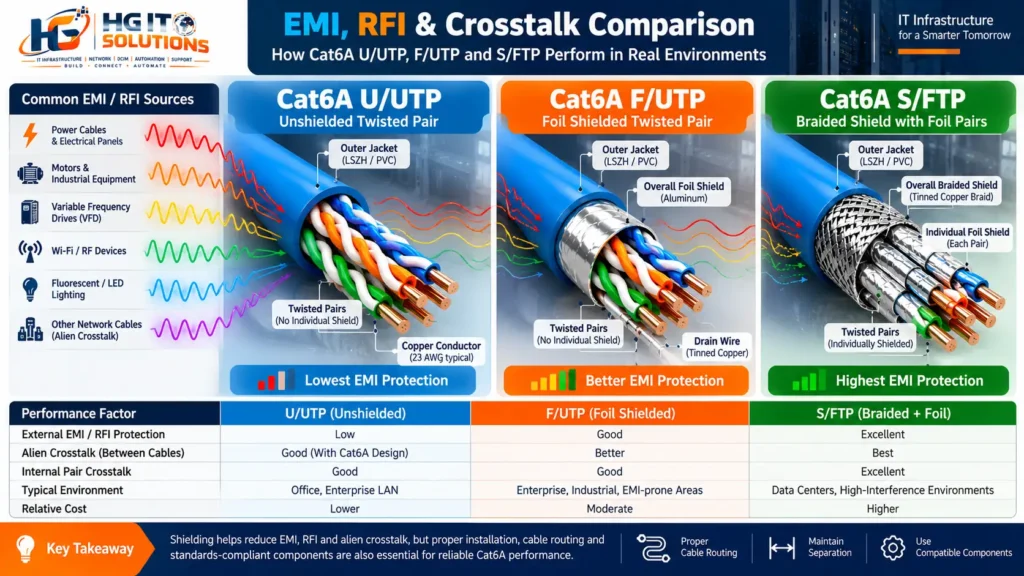
7. Understanding EMI, RFI, and Crosstalk
Shielding decisions are often made because of concerns about electrical interference.
However, not every interference problem has the same cause.
Electromagnetic Interference (EMI)
EMI is unwanted electromagnetic energy that affects electrical or electronic systems.
Potential sources include:
- Electrical motors
- Variable-frequency drives
- Power distribution equipment
- Switching power supplies
- Industrial machinery
- Certain radio-frequency equipment
The actual interference risk depends on field strength, frequency, distance, cable balance, shielding effectiveness, and installation conditions.
Radio Frequency Interference (RFI)
RFI is interference associated with radio-frequency electromagnetic energy.
It can originate from radio transmitters, industrial RF equipment, or other high-frequency sources.
RFI is a subset of electromagnetic interference.
Near-End Crosstalk (NEXT)
NEXT measures unwanted signal coupling between pairs within the cabling channel, evaluated at the near end.
Poor termination, excessive untwisting, and incompatible components can contribute to failures.
Alien Crosstalk (AXT)
Alien crosstalk occurs between different cables.
This is particularly important in high-density installations where many cables run close together.
Cat6A includes performance requirements addressing alien crosstalk for 10GBASE-T applications.
A screened construction can help reduce coupling between neighboring cables, but compliant U/UTP Cat6A systems are also designed to meet the applicable requirements.
Engineering lesson
A cable’s shielding designation alone does not establish its actual EMI immunity.
When screening performance is critical, compare manufacturer test data such as coupling attenuation and transfer impedance where applicable.
Do not assume every S/FTP product outperforms every F/UTP product under all conditions.
8. Grounding and Bonding: The Most Important Part of Shielded Cabling
One of the biggest differences between U/UTP and screened Cat6A cabling is the requirement to manage metallic screen continuity and bonding correctly.
This is an area where installation mistakes can undermine the expected benefits of shielding.
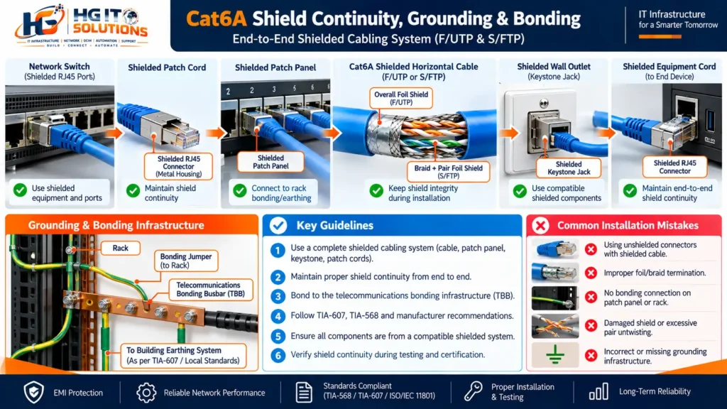
Grounding and bonding are essential considerations in any Cat6A U/UTP vs F/UTP vs S/FTP evaluation. Unlike U/UTP, screened cabling systems require appropriate shield continuity, compatible components, and a properly designed telecommunications bonding infrastructure.
U/UTP grounding considerations
U/UTP cable does not contain a metallic screen requiring termination.
However, the telecommunications installation still needs to comply with applicable electrical safety and equipment bonding requirements.
Unshielded cabling does not eliminate the need for a properly designed telecommunications bonding infrastructure.
F/UTP and S/FTP bonding considerations
A screened cabling system requires compatible components and an appropriate bonding arrangement.
The intended electrical continuity normally includes the screened cable, screened termination hardware, patch panels, and associated equipment interfaces.
The exact design depends on the manufacturer’s system requirements and applicable standards.
A typical conceptual arrangement is:
Network Equipment → Screened Patch Cord → Screened Patch Panel → Screened Horizontal Cable → Screened Outlet → Screened Equipment Cord → Connected Device
The equipment and telecommunications bonding infrastructure must be designed to provide appropriate safety and electromagnetic compatibility.
Does shielded cable need grounding at both ends?
This question is frequently oversimplified.
In properly designed screened structured cabling systems, screen continuity is normally maintained through the connectivity system, with bonding through the designated equipment and telecommunications grounding infrastructure.
However, the precise bonding configuration must follow the applicable standard, manufacturer’s instructions, and site electrical design.
The recommendation to ground every shielded cable at only one end is not a universal rule for Ethernet structured cabling.
Likewise, indiscriminately connecting cable shields to unrelated ground points can introduce safety and performance problems.
For installations involving different buildings, significant potential differences, or uncertain earthing conditions, obtain a qualified electrical and telecommunications bonding assessment.
Fiber optics may be preferable where electrical isolation is required.
Common bonding mistakes
- Using screened cable with incompatible unshielded connectivity.
- Leaving the foil or braid improperly terminated.
- Using screened patch panels without the specified bonding connections.
- Assuming a metallic rack automatically provides adequate bonding.
- Connecting screens to arbitrary electrical points.
- Ignoring differences in grounding potential between buildings.
- Failing to inspect shield continuity during installation.
A shielded system should be treated as a complete engineered installation rather than just a different cable jacket.
9. Is S/FTP Better for 10GbE?
Not automatically.
10GBASE-T requires a cabling channel that meets the relevant transmission performance requirements.
These include parameters such as insertion loss, return loss, crosstalk, and alien crosstalk.
All three Cat6A constructions can meet these requirements.
Example: Two different 10GbE installations
Installation A
A 65-meter Cat6A U/UTP permanent link is installed using compatible components, appropriate cable routing, and correct termination practices.
The link passes the required Category 6A certification tests.
Installation B
A 65-meter Cat6A S/FTP permanent link is installed, but the cable is excessively bent, the connectors are poorly terminated, and the installation fails certification.
Despite having more shielding, Installation B is not the better network infrastructure.
The lesson is simple:
A properly installed and certified Cat6A channel is more important than selecting the most heavily shielded cable.
Shielding should be selected for a defined electromagnetic or project requirement, not as a replacement for installation quality.
10. Cat6A Shielding and High-Power PoE Applications
Power over Ethernet introduces another important design consideration: heat.
Modern IEEE PoE systems can deliver power to wireless access points, IP cameras, access control devices, and other network equipment.
| PoE Type | IEEE Standard | Maximum PSE Power |
|---|---|---|
| Type 1 | IEEE 802.3af | 15.4 W |
| Type 2 | IEEE 802.3at | 30 W |
| Type 3 | IEEE 802.3bt | 60 W |
| Type 4 | IEEE 802.3bt | 90 W |
These figures represent maximum power at the power sourcing equipment, not the power guaranteed at the connected device.
Does shielding reduce PoE heating?
Shielding can affect the thermal characteristics of a cable, but the relationship is not simple enough to rank U/UTP, F/UTP, and S/FTP universally.
PoE heating depends on several factors:
- Copper conductor size and resistance
- Conductor material
- Current carried by each pair
- Cable bundle size
- Ambient temperature
- Cable jacket and insulation construction
- Pathway ventilation
- Installation conditions
Metallic screens may influence heat transfer, but shielding alone does not establish whether a cable is suitable for a high-power PoE application.
Practical scenario: 48 high-power PoE connections
Imagine a network cabinet serving 48 wireless access points.
The installation uses Cat6A horizontal cabling, with multiple cables grouped together in overhead pathways.
Some access points may operate using IEEE 802.3bt power.
Before selecting the cable, engineers should calculate or evaluate the expected current, conductor resistance, bundle configuration, ambient temperature, and manufacturer’s installation limits.
The decision should not be based solely on whether the cable is U/UTP or S/FTP.
A well-designed Cat6A U/UTP system may be suitable, while a screened solution may be appropriate for other environmental reasons.
Important: For high-power PoE installations, use compliant solid-copper cabling and review the manufacturer’s thermal and bundle-size guidance. Avoid copper-clad aluminum conductors for standards-compliant structured cabling.
11. Cat6A Shielding for Data Center Installations
Data centers often have dense cable pathways, multiple network racks, high-capacity switching equipment, and complex power distribution systems.
However, this does not automatically mean every copper cable must be S/FTP.
The correct decision depends on the cabling architecture and environmental requirements.
Scenario A: Dedicated copper pathways in a data center
Consider a data center with structured cabling pathways dedicated to copper network connections.
The copper links connect management switches, infrastructure controllers, selected servers, and network appliances.
Cable pathways are properly designed and separated from power distribution infrastructure.
In this environment, Cat6A U/UTP may be entirely appropriate if the selected system meets performance and installation requirements.
Scenario B: High-density patching areas
A high-density patching environment may contain many adjacent Cat6A channels.
Screened systems can help control electromagnetic coupling and may offer installation advantages in particular designs.
However, the selection should also consider:
- Cable diameter
- Cable tray capacity
- Rack cable management
- Connector density
- Termination accessibility
- Manufacturer system compatibility
- Certification requirements
F/UTP and S/FTP should be compared using actual product specifications rather than assumed cable-size advantages.
Scenario C: Industrial equipment inside a data center facility
Some data center environments include monitoring and control systems near mechanical or electrical equipment.
If copper cabling must pass through electrically noisy areas, screened cabling may deserve consideration.
Nevertheless, physical separation and appropriate routing remain essential.
For particularly challenging environments, fiber optic cabling may offer better electrical isolation.
Practical recommendation
Do not create a project specification stating that all data center copper cabling must be S/FTP without documenting why.
A better specification identifies the required transmission category, electromagnetic environment, cabling system, bonding arrangement, and acceptance tests.
For broader infrastructure planning, see our guide to Cat6 vs Cat6A Ethernet Cable: Differences, Distance, PoE & Installation Best Practices.
12. Installation Challenges: U/UTP vs F/UTP vs S/FTP
Shielded cabling can require additional installation steps.
Cable handling
The installer must maintain the cable’s specified minimum bend radius and maximum pulling tension.
These limits vary by manufacturer and product.
Do not assume all Cat6A cables have the same mechanical limits.
Cable stripping
For U/UTP, the installer removes the outer jacket and prepares the twisted pairs according to the connector manufacturer’s instructions.
For F/UTP and S/FTP, the installer must also prepare the metallic screen correctly.
Incorrect foil removal, braid handling, or screen termination can affect electromagnetic performance.
Pair untwisting
Excessive pair untwisting can negatively affect transmission performance.
Installers should maintain pair geometry as close to the termination as the connector design requires.
Screen termination
Screened connectors commonly provide a mechanism to establish electrical continuity between the cable screen and connector housing.
Follow the specific connector manufacturer’s termination instructions.
Do not assume that touching the screen to a metal surface is sufficient.
Patch panels and patch cords
A screened permanent link should be integrated with the appropriate screened connectivity system.
The complete channel must meet the intended category and system requirements.
Testing
After installation, perform the required certification tests and verify screen continuity where applicable.
Visual inspection alone is insufficient to establish channel compliance.
13. Common Installation Mistakes That Affect Cat6A Performance
The following problems can occur with shielded and unshielded cabling.
Mistake 1: Excessive cable bending
Sharp bends can change cable geometry and negatively affect transmission performance.
Use the product-specific minimum bend radius.
Mistake 2: Excessive pulling tension
Pulling beyond the manufacturer’s limits can deform conductors or damage cable construction.
Mistake 3: Over-tightened cable ties
Excessive compression can affect pair geometry.
Use appropriate cable management methods and avoid crushing cable bundles.
Mistake 4: Mixing incompatible components
Using a Cat6A cable does not guarantee that the completed channel meets Cat6A requirements.
The connectors, patch panels, patch cords, and installation must be compatible with the specified system.
Mistake 5: Poor shield termination
Improper screen termination can reduce the intended electromagnetic protection of screened systems.
Mistake 6: Incorrect bonding
A screened system requires a coordinated bonding design.
Do not improvise grounding connections in the field.
Mistake 7: Ignoring cable temperature
High ambient temperatures and PoE bundle heating can increase insertion loss.
Mistake 8: Skipping certification
A link that negotiates at 10Gbps is not automatically a certified Cat6A channel.
Certification provides evidence of compliance with defined cabling performance limits.
14. How to Test and Certify Cat6A Cabling
Certification is an essential part of a professional structured cabling installation.
A suitable field certifier should be configured for the relevant Category 6A or Class EA test limit, test configuration, and cabling standard.
Important certification measurements
| Test | Purpose |
|---|---|
| Wiremap | Checks conductor connections and wiring faults |
| Length | Verifies link length |
| Insertion Loss | Measures signal attenuation |
| NEXT / PSNEXT | Evaluates near-end crosstalk |
| ACR-F / PSACR-F | Evaluates far-end crosstalk relationships |
| Return Loss | Evaluates impedance-related signal reflections |
| Propagation Delay | Measures signal travel time |
| Delay Skew | Measures timing differences between pairs |
| Alien Crosstalk | Evaluates coupling between separate cables when required |
| Screen Continuity | Checks screen connection integrity for screened systems |
Permanent link vs channel testing
Permanent link certification tests the installed fixed cabling infrastructure using the appropriate test adapters.
Channel certification includes the complete channel configuration within the applicable test arrangement.
The test method must match the project acceptance requirements.
Does every Cat6A installation require alien crosstalk testing?
Not necessarily as a separate field test.
Alien crosstalk field testing requirements depend on the applicable standard, cabling system, manufacturer guidance, and project specification.
Some systems use laboratory-qualified designs or documented compliance methods.
Do not assume that passing ordinary in-channel certification measurements independently proves every alien crosstalk requirement.
Practical handover recommendation
A professional cabling handover should include:
- Cable identification and port mapping
- Test reports
- Failed-link corrective action records
- As-built drawings
- Patch panel schedules
- Manufacturer system information
- Bonding inspection records where applicable
- Final acceptance documentation
This documentation is especially valuable when the network is expanded or modified several years later.
15. Cost Comparison: Is Shielded Cat6A Worth the Investment?
Cable price alone does not represent the complete installation cost.
A proper comparison should include material, installation labor, testing, infrastructure, and future maintenance.
| Cost Factor | U/UTP | F/UTP | S/FTP |
|---|---|---|---|
| Cable material | Often lower | Often higher | Often higher |
| Connector preparation | Generally simpler | Screen preparation | Pair and braid preparation |
| Connectivity accessories | Unscreened system | Screened system | Screened system |
| Bonding requirements | General equipment bonding | Screened-system bonding | Screened-system bonding |
| Installer skill requirements | Standard Cat6A | Screened termination | More complex screened termination |
| Testing | Cat6A certification | Cat6A + screen checks | Cat6A + screen checks |
| Maintenance | Standard practices | Screen continuity considerations | Screen continuity considerations |
These are general tendencies. Product selection, supplier pricing, installation conditions, and labor rates can change the relative costs.
Example: A 500-link enterprise project
Imagine a project with 500 horizontal Cat6A links.
Even a small difference in installed cost per link can become significant across the complete project.
But selecting the cheapest cable without considering environmental requirements can create additional costs through troubleshooting, replacement, or service disruption.
Likewise, selecting the most expensive shielded construction without a technical justification may unnecessarily increase project cost.
The better approach is to compare the total installed system cost against the documented requirements.
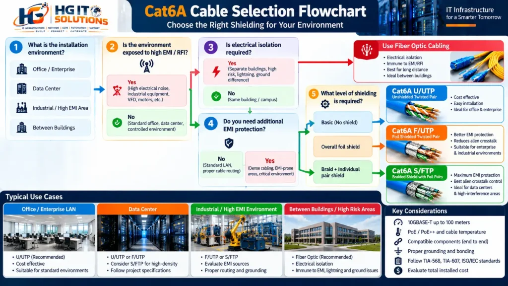
16. Practical Engineering Decision Matrix
Use the following matrix as an initial selection guide.
| Installation Environment | Starting Recommendation | Engineering Consideration |
|---|---|---|
| Standard office LAN | U/UTP | Usually sufficient with proper routing |
| Enterprise 10GbE | U/UTP or F/UTP | Both can meet Cat6A requirements |
| High-density copper pathways | U/UTP, F/UTP or S/FTP | Compare certified systems and pathway capacity |
| Industrial machinery area | F/UTP or S/FTP evaluation | EMI survey and equipment requirements |
| High-power PoE deployment | Any suitable compliant Cat6A construction | Evaluate thermal and bundle conditions |
| Data center management network | U/UTP or screened system | Follow infrastructure specifications |
| Electrically noisy control environment | Screened system or fiber | Evaluate EMI and electrical isolation |
| Between separate buildings | Fiber often preferred | Electrical isolation and surge exposure |
These recommendations are starting points, not substitutes for a project-specific design assessment.
My practical selection approach
Choose Cat6A U/UTP when:
The electromagnetic environment is controlled, pathways are properly designed, and there is no specific requirement for a screened cabling system.
Evaluate Cat6A F/UTP when:
The project requires overall foil screening and a compatible screened infrastructure offers a justified benefit.
Evaluate Cat6A S/FTP when:
The environment or project specification requires additional pair screening and an overall braided screen, with appropriate installation and bonding provisions.
Evaluate fiber optics when:
Electrical isolation, distance, interference exposure, or network architecture makes copper less suitable.
If you are evaluating optical connectivity for a data center, our OM3 vs OM4 vs OM5 Fiber: Which One Should You Use in a Data Center? guide explains how fiber category, distance, and transceiver selection influence infrastructure decisions.
17. Engineering Checklist Before Selecting Cat6A Shielding
Before approving a cabling specification, answer these questions.
- What Ethernet speed and channel distance are required?
- Is the environment exposed to significant EMI or RFI?
- Are cable pathways adequately separated from power infrastructure?
- Is a screened cabling system required by the project specification?
- What Cat6A transmission performance must be certified?
- Are the connectors, patch panels, and patch cords compatible?
- Is the bonding and grounding infrastructure suitable?
- Will the cabling carry high-power PoE?
- What are the cable diameter, bend radius, and pulling tension limits?
- Can the installation team terminate the selected cable correctly?
- Are the required field certification tests clearly specified?
- Does the shielding benefit justify the total installed cost?
Answering these questions before procurement can prevent unnecessary expense and installation problems.
18. Final Recommendation: Which Cat6A Shielding Is Best?
There is no single shielding construction that is best for every network.
Cat6A U/UTP, F/UTP, and S/FTP can all provide reliable 10GBASE-T connectivity when the complete cabling channel meets the required performance standards.
U/UTP is often a practical option for standard enterprise environments where proper pathway design and balanced cabling provide sufficient interference protection.
F/UTP adds overall foil screening and can be useful where a screened cabling system is justified.
S/FTP combines individual pair foil screens with an overall braided screen, making it a candidate for installations with more demanding electromagnetic compatibility requirements.
But more shielding does not automatically mean better network performance.
A poorly installed S/FTP channel can fail certification, while a correctly installed U/UTP channel can meet Cat6A requirements and operate reliably at 10Gbps.
For data center and enterprise infrastructure projects, the most effective approach is to evaluate:
Application + EMI Environment + Cabling Pathway + Bonding + Installation Quality + Certification + Total Cost
Select the cable construction that meets these requirements with an appropriate engineering margin.
A reliable network does not start with choosing the cable that looks most advanced. It starts with selecting and installing a complete cabling system that meets the actual operational requirements.
Frequently Asked Questions
1. What is the difference between Cat6A U/UTP and F/UTP?
U/UTP has no metallic shielding, while F/UTP has an overall foil screen around the four twisted pairs. Both can support 10GBASE-T over a compliant 100-meter Cat6A channel.
2. Is Cat6A S/FTP better than F/UTP?
S/FTP provides a different screening construction with individually foil-shielded pairs and an overall braid. It may be beneficial in demanding electromagnetic environments, but actual performance depends on product design and installation quality.
3. Does Cat6A U/UTP support 10Gbps over 100 meters?
Yes. A standards-compliant Cat6A U/UTP channel can support 10GBASE-T over a channel up to 100 meters, subject to the applicable installation and performance requirements.
4. Does shielded Cat6A require grounding?
Screened cabling systems require appropriate shield continuity and bonding through compatible components and the designated telecommunications bonding infrastructure. The exact arrangement must follow applicable standards and manufacturer instructions.
5. Can I use an unshielded RJ45 connector with S/FTP cable?
It is not recommended for a properly specified screened cabling system. Use compatible screened connectors and termination hardware to maintain the intended screen continuity and system performance.
6. Is S/FTP required for data centers?
No. Data centers can use unshielded or screened Cat6A systems depending on the installation environment, infrastructure design, and project requirements.
7. Which Cat6A cable is best for PoE++?
There is no universal shielding-based answer. Select compliant cable based on conductor resistance, temperature rating, bundle size, ambient conditions, and manufacturer guidance.
8. Is F/UTP easier to install than S/FTP?
F/UTP often requires less complex screen preparation because it has an overall foil screen rather than individual pair foil screens plus an overall braid. Actual installation difficulty depends on the cable and connector design.
9. Can shielded Ethernet cable eliminate all EMI problems?
No. Shielding can reduce electromagnetic coupling, but proper routing, bonding, equipment design, and installation practices remain important. Severe interference environments may require a different cabling architecture.
10. Should I use copper or fiber between buildings?
Fiber is often preferred for connections between separate buildings because optical fiber provides electrical isolation and avoids several copper-related grounding and surge concerns. The final design should consider distance, equipment, route, and applicable codes.
Technical References and Further Reading
For readers who want to explore manufacturer specifications and cabling standards in greater detail, the following resources provide useful starting points.
- Belden — Shielded Cabling Product Reference — Technical product information covering screened cable constructions and Category 6A performance.
 catalog.belden.com
- Fluke Networks — Field certification, copper cable testing, and troubleshooting resources.
- Ethernet Alliance — Ethernet technology and Power over Ethernet educational resources.
- Telecommunications Industry Association — Industry standards and resources relevant to structured cabling and telecommunications bonding.
Relevant standards to consult include ANSI/TIA-568.2-D and applicable amendments, ISO/IEC 11801, ANSI/TIA-607, and IEEE 802.3. Verify the current editions and any local requirements before specifying or certifying an installation.
